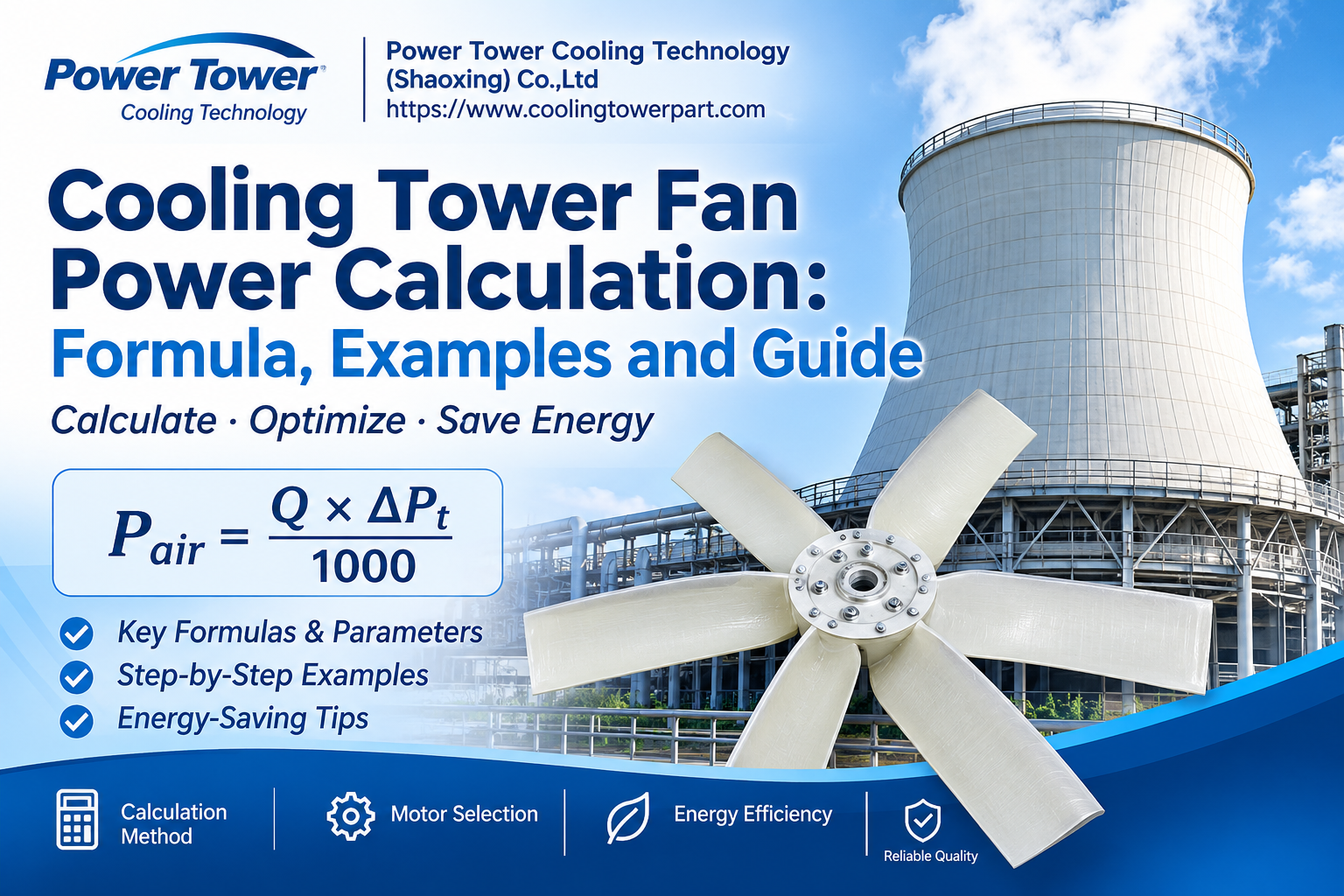
1. Introduction to Cooling Tower Fan Power
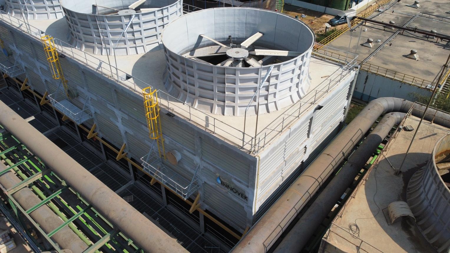
A cooling tower does an important job in industrial facilities: it removes unwanted heat from circulating water and releases that heat into the atmosphere. The fan is one of the key components that makes this process possible. It moves air through the tower, supports heat and mass transfer, and helps maintain the required cooling performance.
But how much power does a cooling tower fan actually need? The answer depends on several factors, including airflow rate, fan pressure, aerodynamic efficiency, motor efficiency, and operating conditions.
Cooling tower fan power calculation helps engineers estimate the required power before selecting a motor or replacing an existing fan. It also helps maintenance teams identify abnormal energy consumption and find opportunities to reduce operating costs.
In this guide, we will explain the main formulas, define the parameters, work through a practical calculation example, and discuss ways to improve fan efficiency.
2. Why Cooling Tower Fan Power Calculation Matters
Choosing a fan motor based only on the capacity of a cooling tower can lead to problems. Two towers with similar cooling capacities may require different fan power because their airflow paths, fan diameters, pressure losses, and operating conditions are not necessarily the same.
An undersized motor may struggle under normal operating conditions. It can overheat, trip frequently, or fail to deliver the airflow needed for cooling. An oversized motor, on the other hand, may increase initial investment and create opportunities for inefficient operation if the system is not properly controlled.
Accurate calculation helps you:
Estimate the power required to move the design airflow.
Select a suitable fan and motor combination.
Compare different fan designs and operating conditions.
Estimate electricity consumption and operating costs.
Identify potential energy-saving opportunities.
Evaluate replacement fans and retrofit projects.
In short, the calculation connects the aerodynamic requirements of the cooling tower with the electrical requirements of its drive system.
3. Understanding the Main Power Terms
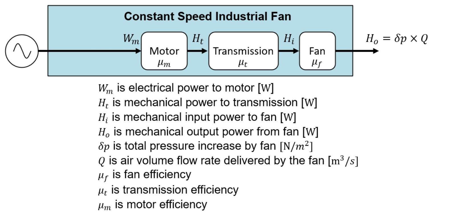
Before using a formula, it is important to understand three different power values. They are related, but they do not mean the same thing.
3.1 Air Power
Air power is the useful power transferred to the air by the fan. It is calculated from the airflow rate and the pressure increase across the fan.
Air power is a theoretical aerodynamic requirement. It does not include the energy lost through fan inefficiency, motor losses, or other drive-system losses.
3.2 Fan Shaft Power
Fan shaft power is the mechanical power that must reach the fan shaft to produce the required airflow and pressure.
Because a real fan is not 100% efficient, the shaft power is higher than the air power. The difference represents energy lost through aerodynamic effects such as turbulence, flow separation, and other internal losses.
3.3 Motor Input Power
Motor input power is the electrical power drawn by the motor to deliver the required mechanical output.
The motor also has losses, so its electrical input power is higher than its mechanical output power. If a belt drive or gearbox is installed, its efficiency must also be considered when calculating the complete system.
Understanding these differences prevents a common selection mistake: treating air power, fan shaft power, and electrical input power as interchangeable values.
4. Cooling Tower Fan Power Calculation Formula
The basic calculation starts with the relationship between airflow and pressure.
4.1 Basic Air Power Formula
When airflow is measured in cubic meters per second and pressure is measured in pascals, the air power formula is:
[
P_{\text{air}}=\frac{Q\times\Delta P_t}{1000}
]
Where:
(P_{\text{air}}) = air power in kW
(Q) = airflow rate in m³/s
(\Delta P_t) = fan total pressure rise in Pa
The formula shows that air power increases when either airflow or pressure increases.
For example, if a fan moves more air through the same pressure resistance, it needs more power. If the airflow remains constant but the required pressure rises, the power requirement also increases.
Important: Use pressure values that match the fan performance data and the selected calculation method. Total pressure and static pressure are not identical. Do not substitute one for the other without checking the fan manufacturer's performance definitions.
4.2 Fan Shaft Power Formula
To calculate the mechanical power required at the fan shaft, divide air power by fan total efficiency:
[
P_{\text{shaft}}=\frac{P_{\text{air}}}{\eta_f}
]
Where:
(P_{\text{shaft}}) = fan shaft power in kW
(P_{\text{air}}) = air power in kW
(\eta_f) = fan total efficiency expressed as a decimal
For example, an efficiency of 72% should be entered as 0.72, not 72.
A lower fan efficiency means that more shaft power is needed to deliver the same airflow and pressure.
4.3 Motor Input Power Formula
If the motor is directly coupled to the fan, the estimated motor electrical input power is:
[
P_{\text{motor input}}=\frac{P_{\text{shaft}}}{\eta_m}
]
Where:
(P_{\text{motor input}}) = electrical input power in kW
(P_{\text{shaft}}) = required mechanical output in kW
(\eta_m) = motor efficiency expressed as a decimal
For a belt-driven or geared arrangement, include the drive efficiency:
[
P_{\text{motor input}}=
\frac{P_{\text{shaft}}}{\eta_d\times\eta_m}
]
Here, (\eta_d) represents the efficiency of the transmission system. Use the appropriate drive efficiency for the actual equipment rather than assuming that every drive has the same losses.
5. Key Parameters Required for Calculation
A formula is only as reliable as the data entered into it. Before calculating cooling tower fan power, collect the following information.
5.1 Airflow Rate
Airflow rate describes the volume of air passing through the fan per unit of time. It is commonly expressed in m³/s or m³/h.
If the airflow is provided in m³/h, convert it to m³/s before using the formula:
[
Q_{\text{m}^3/\text{s}}=\frac{Q_{\text{m}^3/\text{h}}}{3600}
]
For example, 360,000 m³/h is equal to 100 m³/s.
Do not confuse the cooling tower's nominal capacity with its airflow rate. Cooling capacity and airflow are related through the tower's thermal design, but they are different engineering parameters.
5.2 Fan Pressure
Fan pressure represents the resistance the fan must overcome while moving air through the cooling tower.
Pressure losses may come from the air inlet, fill, drift eliminators, louvers, fan cylinder, discharge arrangement, and other components. The actual system resistance depends on the tower design and operating condition.
Use the fan duty point and the pressure definition supplied by the fan manufacturer or system designer. A pressure value taken from an unrelated operating point can produce a misleading power estimate.
5.3 Fan Efficiency
Fan efficiency describes how effectively the fan converts mechanical shaft power into useful air power.
It is affected by blade geometry, blade pitch, rotational speed, fan diameter, operating point, installation quality, and airflow uniformity.
A fan operating far from its best-efficiency region may consume more power than expected. For a reliable calculation, use performance data for the specific fan model and duty point.
5.4 Motor Efficiency
Motor efficiency measures how much electrical input power is converted into mechanical output power.
It varies with motor design, rated power, load, speed, and operating condition. Use the motor manufacturer's efficiency data whenever possible.
Remember that motor efficiency is not the same as fan efficiency. Both values are needed when estimating electrical power from airflow and pressure.
6. Step-by-Step Cooling Tower Fan Power Calculation
You can follow this sequence for a basic engineering estimate:
Confirm the required cooling tower airflow.
Convert the airflow into m³/s if necessary.
Obtain the fan total pressure at the required duty point.
Calculate air power using airflow multiplied by total pressure.
Divide air power by fan total efficiency to find fan shaft power.
Account for belt or gearbox losses if they are present.
Divide the required motor mechanical output by motor efficiency to estimate electrical input power.
Select a motor rating based on the actual required shaft output, applicable design margin, starting conditions, and manufacturer recommendations.
Check that the selected fan and motor operate within their permitted performance and mechanical limits.
This process gives you a more useful result than selecting a motor simply because another cooling tower of a similar size uses the same rating.

7. Practical Cooling Tower Fan Power Calculation Example
Let's work through a simplified example to make the formulas easier to understand.
Assume an industrial cooling tower has the following design data:
| Parameter | Assumed Value |
| Airflow rate | 120 m³/s |
| Fan total pressure rise | 180 Pa |
| Fan total efficiency | 72% |
| Motor efficiency | 93% |
| Drive arrangement | Direct drive |
These values are illustrative. Actual design values must come from the cooling tower system requirements and the fan and motor performance data.
7.1 Calculate Air Power
Start with:
[
P_{\text{air}}=\frac{Q\times\Delta P_t}{1000}
]
Insert the values:
[
P_{\text{air}}=\frac{120\times180}{1000}
]
[
P_{\text{air}}=21.6\text{ kW}
]
The fan must transfer approximately 21.6 kW of useful aerodynamic power to the air at this operating point.
7.2 Calculate Fan Shaft Power
The fan efficiency is 72%, or 0.72.
[
P_{\text{shaft}}=\frac{21.6}{0.72}
]
[
P_{\text{shaft}}=30\text{ kW}
]
The fan therefore requires approximately 30 kW of mechanical power at its shaft under the assumed conditions.
7.3 Calculate Motor Input Power
The motor efficiency is 93%, or 0.93.
[
P_{\text{motor input}}=\frac{30}{0.93}
]
[
P_{\text{motor input}}\approx32.26\text{ kW}
]
The estimated electrical input power is approximately 32.26 kW at this duty point.
7.4 Select the Appropriate Motor Rating
The calculated 30 kW is the required mechanical output at the fan shaft. It is not the same as the motor's electrical input power.
For a direct-drive arrangement, the selected motor must be capable of delivering at least the required shaft output under the specified operating conditions. Engineers may consider a suitable design margin and then choose an available standard motor rating.
A 37 kW motor might be a candidate in this illustrative example, but it should not be selected automatically. Confirm the fan's maximum absorbed power, service conditions, starting requirements, motor loading, applicable standards, and manufacturer's recommendations before finalizing the rating.
8. How Cooling Tower Fan Diameter Affects Power
Fan diameter has a significant influence on airflow, pressure capability, rotational speed, and power demand.
A larger fan can move a greater volume of air at an appropriate operating speed, but a larger diameter does not automatically mean lower power consumption. The result depends on the complete aerodynamic design and the system duty point.
When comparing different fan diameters, consider:
Required airflow and pressure.
Fan rotational speed.
Blade geometry and pitch.
Tip clearance and fan cylinder design.
Installation space and structural limitations.
Fan efficiency at the actual operating point.
A properly matched fan can deliver the required airflow without unnecessary energy consumption. However, replacing a fan with a different diameter without checking the system can create vibration, clearance, structural, and performance problems.
9. How Blade Pitch Angle Affects Fan Power
Blade pitch determines the angle at which each blade meets the airflow. It has a direct effect on the aerodynamic load of an axial fan.
Increasing the blade pitch generally increases airflow and power demand within the fan's operating range. Reducing the pitch usually lowers airflow and power demand.
But is a larger pitch always better? Not necessarily.
If the pitch is too high, the motor may become overloaded. If it is too low, the fan may not deliver enough air to meet the cooling tower's thermal requirements.
For adjustable-pitch fans, all blades should be set consistently according to the manufacturer's instructions. Check the angle at the specified measurement position, because blade pitch readings can differ depending on the reference method.
After adjustment, verify motor current, vibration, fan performance, and cooling tower operating conditions. Never change the blade angle simply to reduce electrical power without confirming that the tower still achieves its required cooling duty.
10. Axial Fan vs. Centrifugal Fan Power
Axial and centrifugal fans move air in different ways, so their power requirements and suitable applications can differ.
Axial fans move air mainly parallel to the fan shaft. They are widely used in mechanical-draft cooling towers because they can handle large airflow volumes and are suitable for many relatively low-pressure applications.
Centrifugal fans accelerate air outward through the impeller and discharge it in a direction that is generally different from the inlet flow. They can be useful where the system requires a different pressure and ducting arrangement.
Neither fan type is automatically more efficient in every application. Compare the actual duty points, efficiency curves, noise limits, installation conditions, and absorbed power. The correct choice is the one that meets the cooling tower's airflow and pressure requirements with suitable reliability and energy performance.
11. Cooling Tower Fan Power Consumption and Energy Costs
Once you know the electrical input power, you can estimate energy consumption.
The basic formula is:
[
E=P_{\text{input}}\times t
]
Where:
(E) = electrical energy in kWh
(P_{\text{input}}) = electrical input power in kW
(t) = operating time in hours
Using the example above, assume the fan draws an average of 32.26 kW and operates for 10 hours:
[
E=32.26\times10=322.6\text{ kWh}
]
If the electricity price is $0.12 per kWh, the estimated energy cost is:
[
322.6\times0.12=$38.71
]
This is a simplified estimate. Actual electricity bills may also include demand charges, time-of-use rates, taxes, and other fees.
For a more accurate operating-cost analysis, use measured electrical power over representative operating periods rather than relying only on the motor nameplate rating.
12. Common Factors That Increase Fan Power
If a cooling tower fan suddenly consumes more electricity, do not assume that the motor is the only problem. Several mechanical and aerodynamic conditions can increase power demand or reduce cooling performance.
Common causes include:
Incorrect blade pitch: Excessive pitch can increase aerodynamic loading and motor current.
Fan imbalance: Uneven mass distribution can cause vibration and mechanical stress.
Dirty airflow passages: Deposits or obstructions can change system resistance and reduce airflow.
Damaged blades: Cracks, deformation, or surface deterioration can affect aerodynamic performance and safety.
Poor installation: Incorrect alignment, clearances, or mounting can affect fan operation.
Drive problems: Belt tension, bearing condition, gearbox condition, or coupling alignment can influence system performance.
Unstable operating conditions: Changes in airflow demand, water temperature, ambient conditions, or control settings can alter the fan duty point.
The best troubleshooting approach is to compare current measurements with the original design data and previous operating records.
13. How to Reduce Cooling Tower Fan Power Consumption
Reducing fan power is not simply a matter of slowing the fan down. You need to maintain the required cooling performance while avoiding unnecessary energy use.
13.1 Optimize Fan Blade Pitch
Check whether the installed blade pitch matches the design specification. For adjustable-pitch fans, a properly verified adjustment may help match airflow to the cooling tower's actual duty.
Do not make adjustments without checking motor loading and thermal performance.
13.2 Maintain Proper Fan Balance
A balanced fan operates with less vibration and reduced mechanical stress. Inspect the blades, hub, fasteners, and mounting arrangement.
If vibration is detected, identify its cause before carrying out balancing work. Dirt buildup, blade damage, loose connections, and bearing problems may all contribute.
13.3 Improve Airflow Conditions
Keep air inlets, louvers, fill passages, drift eliminators, and discharge areas in suitable condition.
Air recirculation and uneven airflow can reduce cooling tower effectiveness. Correcting these conditions may improve system performance without simply increasing fan speed.
13.4 Use Variable Frequency Drives
A variable frequency drive (VFD) can adjust fan speed to match changing cooling demand.
For many variable-speed fan applications, reducing speed can produce substantial power savings. Under the idealized fan affinity laws, for a geometrically unchanged fan operating in a comparable system:
Airflow is approximately proportional to rotational speed.
Pressure is approximately proportional to rotational speed squared.
Power is approximately proportional to rotational speed cubed.
For example, reducing fan speed to 80% of its original value gives an idealized power ratio of:
[
0.8^3=0.512
]
This suggests approximately 51.2% of the original power under ideal affinity-law conditions. Real cooling tower savings may differ because of system characteristics, control requirements, motor and drive losses, and changing operating points.
Always confirm that the motor, fan, gearbox, and control system are suitable for variable-speed operation.
14. Common Calculation Mistakes to Avoid
Even a simple formula can produce an incorrect result when the input data or units are wrong.
Watch out for these common mistakes:
Mixing airflow units: Do not enter m³/h directly into a formula that requires m³/s.
Confusing static and total pressure: Use the pressure definition that matches the fan performance data.
Ignoring fan efficiency: Air power is not the same as fan shaft power.
Ignoring motor efficiency: Mechanical output and electrical input are different values.
Forgetting drive losses: Include belt or gearbox efficiency when applicable.
Selecting a motor from input power alone: Motor rated output should be checked against the required mechanical shaft load.
Using nominal tower capacity as airflow: Cooling capacity cannot directly replace the airflow value in the power formula.
Ignoring operating conditions: Actual fan performance can change with air density, temperature, elevation, and system resistance.
A good calculation should clearly state its units, assumptions, duty point, and efficiency values.
15. Cooling Tower Fan Power Calculation Checklist
Before approving a fan or motor selection, review the following information:
Required airflow rate and its measurement units.
Fan total pressure at the design duty point.
Fan total efficiency at that duty point.
Motor efficiency and rated mechanical output.
Direct-drive, belt-drive, or gearbox arrangement.
Fan diameter, rotational speed, and blade configuration.
Blade pitch and manufacturer's operating limits.
Maximum absorbed power across the expected operating range.
Electrical supply, starting method, and control requirements.
Mechanical loads, vibration limits, and installation clearances.
Cooling tower thermal performance requirements.
This checklist is useful for new installations, fan replacements, and cooling tower retrofit projects.
16. Choosing Reliable Cooling Tower Fan Components
A correct power calculation is only one part of a reliable cooling tower fan system. The fan blades, hub, drive arrangement, motor, and supporting structure must work together.
When selecting replacement fan components, check the original fan diameter, blade count, blade profile, pitch range, hub connection, rotational speed, and required airflow. Do not assume that two blades with similar external dimensions will have the same aerodynamic performance.
Material selection also matters. FRP (fiber-reinforced plastic) fan blades are used in many industrial cooling tower applications because they can offer a combination of low weight, corrosion resistance, and structural strength. However, the correct material and blade design depend on the operating environment and mechanical requirements.
Power Tower Cooling Technology (Shaoxing) Co.,Ltd focuses on cooling tower components and related replacement solutions. When evaluating cooling tower fan components, buyers should provide the existing fan model, diameter, blade quantity, hub details, operating speed, and available performance data. These details help suppliers assess compatibility and reduce the risk of selecting unsuitable replacement parts.
You can learn more about cooling tower components and related products at:
Website: https://www.coolingtowerpart.com
For a replacement project, it is always better to compare technical specifications and operating requirements than to select components based only on appearance or price.
17. Frequently Asked Questions (FAQs)
17.1 What Is the Formula for Cooling Tower Fan Power Calculation?
The basic air power formula is:
[
P_{\text{air}}=\frac{Q\times\Delta P_t}{1000}
]
When airflow is in m³/s and fan total pressure is in Pa, the result is in kW. Divide air power by fan efficiency to estimate fan shaft power.
17.2 How Do I Calculate Cooling Tower Fan Motor Power?
First calculate air power from airflow and pressure. Divide it by fan efficiency to obtain the required fan shaft power. Then account for drive efficiency, if applicable, and motor efficiency to estimate electrical input power.
The motor's rated mechanical output must be selected to meet the required shaft load under the actual operating conditions.
17.3 Does a Larger Cooling Tower Fan Use More Power?
Not necessarily. A larger fan may move more air, but power depends on airflow, pressure, efficiency, rotational speed, and system resistance. Compare complete fan performance data rather than diameter alone.
17.4 How Does Fan Blade Pitch Affect Power Consumption?
Increasing blade pitch generally increases airflow and fan loading within the operating range. This often increases power demand. The correct setting must balance airflow requirements, motor loading, and cooling performance.
17.5 Can a VFD Reduce Cooling Tower Fan Energy Consumption?
Yes. A VFD can reduce fan speed when the cooling demand is lower. Because fan power can vary approximately with the cube of speed under ideal affinity-law conditions, speed control can offer significant savings. Actual savings depend on the system and operating conditions.
17.6 Why Is My Cooling Tower Fan Drawing More Current Than Expected?
Possible causes include excessive blade pitch, increased system resistance, fan damage, imbalance, drive problems, or incorrect motor selection. Check motor current alongside fan speed, vibration, airflow, and operating conditions.
17.7 Is Fan Shaft Power the Same as Motor Power?
No. Fan shaft power is the mechanical power required at the fan shaft. Motor electrical input power is higher because the motor has conversion losses. If a belt or gearbox is used, transmission losses must also be considered.
18. Conclusion
Cooling tower fan power calculation is essential for selecting suitable fans and motors, estimating electricity consumption, and improving system efficiency. The basic process is straightforward: calculate air power from airflow and pressure, account for fan efficiency to find shaft power, and then consider motor and drive efficiencies to estimate electrical input.
However, accurate results depend on reliable operating data. Airflow, pressure, fan efficiency, motor performance, blade pitch, and installation conditions all matter.
For cooling tower fan replacement or retrofit projects, always check the complete fan system rather than selecting a motor or blade in isolation. Matching the fan components to the actual operating requirements can help maintain cooling performance, reduce unnecessary energy use, and support long-term reliability.
For cooling tower components and replacement-part information, visit Power Tower Cooling Technology (Shaoxing) Co.,Ltd at https://www.coolingtowerpart.com.


